
First, locate the 10‑amp fuse under the steering‑wheel controls and the relay in the engine‑bay fuse box; use a digital multimeter to confirm 12 V on both ends of the fuse and listen for a click when you toggle the AC, swapping the relay if it doesn’t click. Next, inspect the resistor pack that sets blower speed, looking for burn marks or corrosion, and test each resistor for continuity with a multimeter. Then, disconnect the motor plug and measure the voltage on pins 4‑5 (≈115 V) or pins 1‑8 (≈21‑28 V); no voltage points to wiring or coil issues, while a direct battery jump can confirm motor health. After that, check the fan, bearings, and vents for dust, debris, or bent blades that could block rotation. Finally, run advanced diagnostics by measuring winding continuity, verifying PWM signals from the control module with an oscilloscope, and confirming capacitor values against the service manual. Continuing will reveal deeper diagnostic steps.
Quick Tips
- Verify the 10 A fuse under the steering wheel and the AC relay in the engine‑bay fuse box; replace if blown or faulty.
- Inspect the resistor pack and its wiring for burns, corrosion, or open circuits; test each resistor with a multimeter.
- Measure voltage at the motor plug (pins 4‑5 for 115 V or pins 1‑8 for 21‑28 V); no voltage indicates wiring or coil failure.
- Check the blower fan, bearings, and vents for obstructions, dust, or bent blades that could prevent free rotation.
- Use a scan tool or oscilloscope to confirm the control module’s PWM signal and continuity of motor windings; replace defective components.
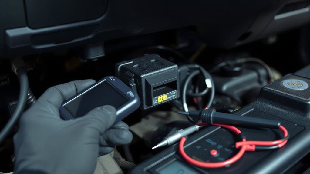
Check the Fuse and Relay When Your Car Blower Isn’t Working

Where’s the problem? First, locate the 10‑amp fuse under the steering‑wheel controls and the relay in the engine‑bay fuse box. Use a digital multimeter to verify 12 V on both ends of the fuse; no voltage means it’s blown.
Listen for a click when you toggle AC; if the relay doesn’t click, swap it with an identical one. Replace any faulty fuse, then retest the blower circuit. Also, check the wiring for any loose or corroded connections that could prevent power from reaching the motor. Be sure to inspect related components like the fuse and relay and their mounting for signs of wear or corrosion.
Inspect the Resistor Pack and Speed Wiring for Faults
A resistor pack controls the blower motor’s speed by adding specific amounts of resistance for each setting, so any fault in the pack or its wiring will limit the fan to a single speed or stop it entirely.
Inspect the pack for burn marks, corrosion, or debris; test each resistor with a multimeter for open circuits.
Examine wiring for shorts, damaged insulation, and loose connectors, and verify that the thermal fuse shows continuity.
Replace damaged components and clean the area to prevent overheating.
Measure Voltage at the Motor Plug and Run a Direct Power Test
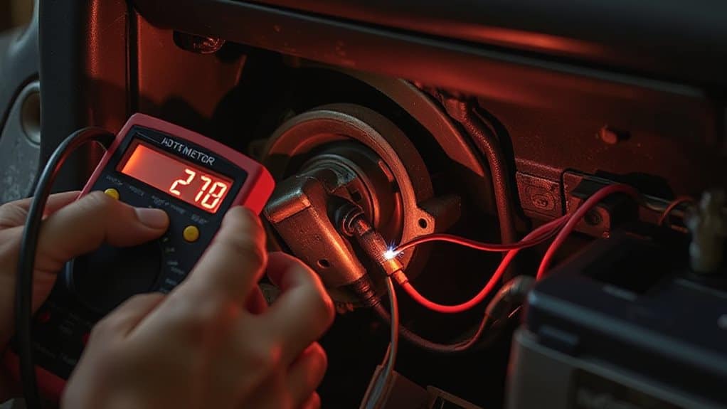
Measuring the voltage at the motor plug and performing a direct power test lets you quickly verify whether the blower motor itself is functional or if the problem lies elsewhere in the control circuit. Turn off the breaker, disconnect the plug, and set the multimeter to AC or DC as appropriate. Probe pins 4‑5 for 115 V or pins 1‑8 for 21‑28 V. No voltage suggests wiring or coil failure; correct voltage with a non‑running motor points to a defective motor. A direct battery jump shows if the motor spins, confirming its condition. For replacement motors, consider using OEM-equivalent parts or reputable brands to ensure reliable performance.
Examine the Fan, Bearings, and Vents for Mechanical Obstructions
You’ll start by inspecting the fan, bearings, and vents for any mechanical obstructions that could impede the blower motor’s operation. Look for dust, debris, or pet hair on the blower wheel; remove buildup to restore free spin. Check blades for bends or misalignment, and feel for resistance when turning the wheel manually. Examine bearings for wear, squealing, or lack of lubrication, and verify that air filters and vents are clear of clogs, dust, or obstructions. Regular maintenance and inspections, including monitoring tread depth and checking for visible damage, help ensure overall safety and prevent failures.
Run Advanced Diagnostics to Verify the Motor and Control Module
Ever wonder how to confirm that the blower motor and its control module are truly functional before replacing parts? First, disconnect the motor and check continuity between its terminals; near‑zero ohms means intact windings. Then use a scan tool or oscilloscope to verify the control module’s PWM signal matches specifications. Test the relay’s click and voltage, and confirm the fuse shows continuity. Finally, measure resistor values and capacitor capacitance against the service manual. Also consider the vehicle’s roof rack weight capacity when determining safe load limits for transporting replaced components.
Wrapping Up
By confirming the fuse, relay, resistor pack, and wiring are intact, you eliminate the most common electrical causes. Measuring voltage at the motor plug and performing a direct power test verifies whether the motor itself receives power. Inspecting the fan, bearings, and vents ensures no mechanical blockage impedes rotation. Finally, advanced diagnostics on the motor and control module pinpoint deeper faults, allowing precise repairs and restoring full blower functionality.


