Check the switched 12‑V hot wire on the GM HEI distributor, confirming it drops from 12 V to about 9 V when you crank the engine; a constant‑hot condition means you’re tapping the battery wrong. Verify the engine ground to battery negative is solid, measuring less than 0.5 V drop while cranking, and clean all ground straps and contacts. Inspect the cap and rotor for cracks, red dust, or corrosion, and clean or replace them if needed. Measure coil resistance (0.6–1.5 Ω) and magnetic pickup resistance (500–1500 Ω) with a multimeter, and test for a steady blue spark while cranking, ensuring battery voltage stays above 10.5 V. If these steps don’t restore spark, you’ll discover how to isolate the hot wire with a jumper and replace faulty parts.
Quick Tips
- Verify ignition‑switched 12 V at the BAT terminal; voltage should be ~12 V with key on and drop no more than ~9 V while cranking.
- Confirm solid engine ground to battery negative; measure ≤0.5 V drop during crank and ensure ground strap and chassis point are clean and tight.
- Inspect the HEI cap, rotor, and terminals for cracks, corrosion, or carbon buildup; clean or replace damaged components.
- Test coil and pickup resistance (coil ≈ 0.6–1.5 Ω, pickup ≈ 500–1500 Ω) and ensure the module receives proper 12 V and internal resistance is within spec.
- Clean all connectors, apply dielectric grease, and secure locking pins; replace faulty HEI module or wiring if spark still absent.
Confirm Switched 12‑V Hot Wire for GM HEI Distributor
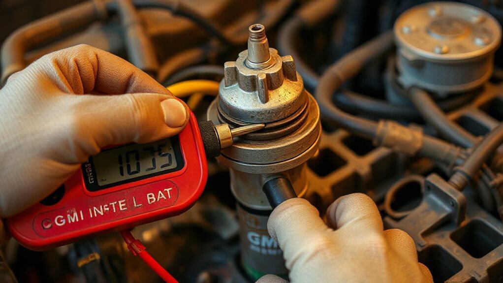
The first step in getting a GM HEI distributor to spark is to verify that you’ve connected a switched 12‑volt hot wire rather than a constant‑hot source. Locate the unused ignition‑on connector in the fuse box, usually a pink wire, and run 12‑gauge wire from that point to the BAT terminal on the distributor cap. Test with the key on; you should see full 12 V, dropping to about 9 V during crank, which is acceptable. Avoid tapping directly into the battery, as that creates a constant‑hot condition that prevents engine shutdown. Ensure the wire passes through a firewall hole cleanly and that the connector locks securely, preventing mis‑orientation. Disconnect the battery before any wiring work to protect yourself and the vehicle’s electronics. HEI systems can run on very low voltage during cranking. Proper corrosion prevention and rust treatment on chassis and terminals helps maintain reliable electrical connections, especially where grounding is critical, so consider using rust prevention products if terminals show corrosion.
Verify Engine Ground to Battery Negative
You should start by checking that the engine ground strap connects solidly to the battery’s negative terminal, because any corrosion or loose bolt adds resistance and can prevent the starter from receiving full voltage. Clean the metal‑to‑metal contacts with a wire brush, tighten the bolts, and then measure the voltage drop while cranking; a reading under 0.5 V indicates a good ground, while higher values point to a faulty connection. If the drop is excessive, replace the strap or re‑route a heavy‑gauge jumper directly from the battery negative post to the engine block to restore proper grounding.
Grounding Ground and Battery
Ground integrity is the backbone of a reliable ignition system, so verifying the engine ground to the battery negative is essential before any spark‑related diagnostics. Measure voltage drop between the negative post and engine ground while the engine is cranked; 0.2 V or less indicates a solid connection. Inspect the ground strap for corrosion, wear, or loose clamps, and test continuity at each chassis point to ensure near‑zero resistance.
Clean Metal‑to‑Metal Contact
A solid metal‑to‑metal connection between the engine ground strap and the battery’s negative post is essential for a reliable ignition circuit. Inspect for corrosion, paint, or rust; scrape away debris with a wire brush or baking‑soda solution, then dry fully. Apply dielectric grease, re‑torque the strap, and verify voltage drop stays below 0.2 V during cranking.
Inspect GM HEI Distributor Cap & Rotor for Damage
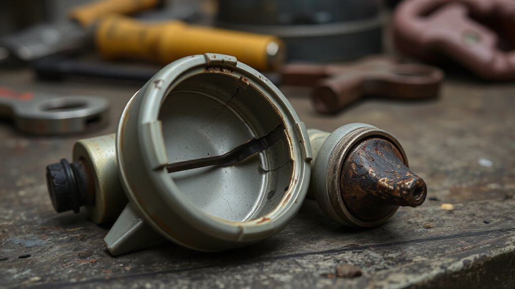
What signs should you look for when examining a GM HEI distributor cap and rotor for damage? Check for cracks in the cap, especially after cold‑heat cycles; red dust inside signals arcing. Look for black carbon buildup on contacts and rotor tip, which disrupts voltage. Inspect terminals for greenish corrosion or pitting. Examine the rotor for wear, cracks, or a melted tip, all of which can cause misfires or no‑start conditions. Also consider checking related electrical systems for voltage surges that can cause arcing or false fault signals.
Measure Coil Resistance in GM HEI Distributor
Where do you start when checking coil resistance in a GM HEI distributor? Set the multimeter to ohms, zero it, then touch the red and yellow terminals; expect 0.6‑1.5 Ω.
Remove the coil with a 1/4‑inch nut driver, connect the negative lead to the black ring and positive to the coil bottom; read 6‑10 kΩ.
Verify connections, follow the specified ranges, and note any deviation.
High-speed reversing is unsafe for stability and control, so prioritize slow, controlled checks when working around vehicles and vehicle stability.
Check Spark at Cap While Rotating Engine?
When you crank the engine, watch the spark at the distributor cap to confirm that the ignition coil is firing correctly. Position a spark tester between the plug wire and plug, ensure the battery reads above 10.5 V, and keep fuel away. Observe a steady blue arc jumping the gap; if it’s absent, the coil isn’t delivering voltage.
Verify the cap and rotor are clean, free of cracks, and spin freely, while checking ground connections and voltage fluctuations on the pink wire. This confirms proper ignition timing and coil output.
Regular maintenance of moving components like the distributor and tracks can prevent wear that leads to failures, so inspect for worn components during your check.
Diagnose Ignition Module When Coil Is Good
First, check that the ignition module is receiving a solid 12‑volt supply; you can verify this with a multimeter on the power lead while the key is in the “on” position.
Next, measure the module’s internal resistance and compare it to the manufacturer’s specifications, because a reading that’s too high or too low usually signals a failed component.
If the voltage is present and the resistance is out of range, replace the faulty module before moving on to other parts.
Confirm 12‑Volt Presence
How do you verify that the ignition module is actually receiving the 12‑volt supply before you blame the coil? Connect a test light or multimeter to the module’s power terminal, ground it to battery negative, and turn the key to the “on” position without cranking. You should read roughly 12 V; any lower reading points to wiring, ground, or upstream module faults, not the coil.
Measure Module Resistance
Where do you start when you need to confirm that the ignition module itself is healthy, assuming the coil checks out? Set your multimeter to ohms, use the smallest range, and zero it. Measure primary resistance after disconnecting the module and coils; expect 0.4‑2 Ω, subtracting 0.2 Ω lead resistance. Then measure secondary resistance on a 0‑10 kΩ range, expecting 6‑15 kΩ, swapping probes to verify consistency. Compare both values to the repair manual; an infinite or out‑of‑spec reading signals a faulty module.
Replace Faulty Module
Ever wonder why a perfectly good coil still leaves you without spark? Verify the module receives 12 V at the red wire; if voltage is missing, fix wiring before replacing. Check ground resistance from the fixing screw to chassis; a poor earth will stop the module. Measure coil primary resistance—must exceed 1.5 Ω. If all tests point to the module, swap it with a known good unit and retest.
Test Magnetic Pickup Coil in GM HEI Distributor
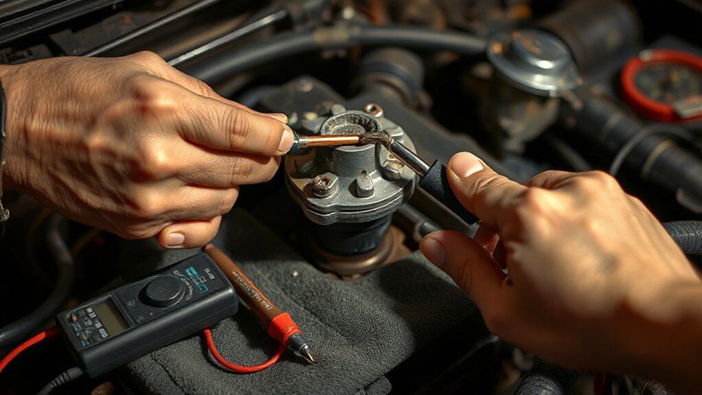
A magnetic pickup coil in a GM HEI distributor is a small copper winding that generates an AC pulse each time the rotor’s magnet passes it, and checking its resistance and continuity is the first step in diagnosing ignition problems.
Disconnect the coil leads, measure 500‑1500 Ω between terminals, verify infinite ohms to ground, wiggle wires while monitoring, and confirm steadiness during vacuum.
Replace the coil if readings fall outside spec.
The Chevy 350 small block is a widely used engine in many GM vehicles, and its fully dressed weight can affect handling and installation considerations.
Run Temporary Jumper Test to Isolate Hot Wire
The temporary jumper test lets you quickly decide whether the distributor’s hot‑wire (B+ terminal) is supplying battery voltage to the ignition module. Connect a short, insulated wire from the battery positive post directly to the B+ terminal, then verify 12 V with a multimeter or test light.
Ground the housing to a clean engine spot, secure the negative lead, and crank the engine. If the test light glows and spark returns, the original hot‑wire is faulty; if not, the module, coil, or pickup likely needs further inspection.
Secure Wiring and Clean Connectors on GM HEI Distributor
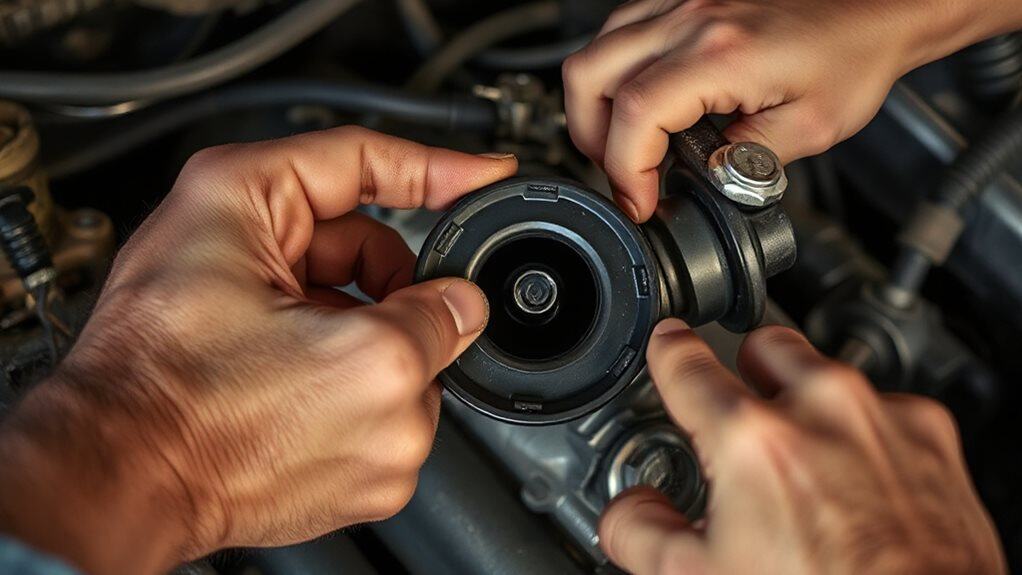
You should verify that each wire from the distributor base plug mates securely with the locking connector block, because a loose BAT (B+) or TACH (C‑) connection will cause voltage drop and prevent the coil from firing. Clean any corrosion on the three‑blade terminals with electrical contact cleaner, then check that resistance between BAT and TACH is under 1 Ω to confirm a low‑impedance path. Finally, make sure the grounding clip and coil wires are firmly attached to a paint‑free chassis point, as a poor ground will also stop the HEI from generating spark. Also check the engine ID tag location under the coil attaching bolts to confirm you have the correct HEI setup for your engine model.
Wiring Connections
Why worry about intermittent spark when a simple wiring check can restore full ignition performance? Verify each wire’s color and destination: white to the pickup coil on the W pin, green to the G pin, pink to the BAT terminal supplying 12 V, brown to ground, and yellow as the negative coil lead. Confirm the three‑wire connector locks firmly into the cap, that the BAT lead is ignition‑switched, and that the brown ground shows under 1 Ω resistance to TACH. Assure the 12‑gauge power wire is solid and the middle pin grounds the module.
Clean Connector Contacts
Where do you start when the HEI distributor’s spark falters? Disconnect the battery, then spray electrical connector cleaner into each hole and work a pipe cleaner through the terminals. File male and female pins with the IPA Tools 8048, starting with the dirtiest, until copper shines. Flush out oil and grime, let everything dry, apply a thin dielectric grease coat, and snap the cap back securely.
Replace Faulty Parts and Apply Heat‑Paste to New Module
A faulty HEI module can cause the distributor to overheat, so replacing it and applying the correct heat‑paste is essential for reliable operation. First, clean the mounting pad with brake cleaner, then spread a thin, even layer of titanium‑dioxide‑based thermal grease—Arctic MX‑4 works well—on the module bottom. Apply dielectric grease only to the spade terminals, align the 4‑pin harness, and secure the screws. Avoid excess paste to prevent air pockets.
Wrapping Up
By confirming the 12‑V hot wire, grounding, and cap/rotor integrity, you’ll locate most GM HEI distributor failures. Measuring coil resistance and testing the magnetic pickup verify internal circuitry, while a temporary jumper isolates the hot wire for quick diagnostics. Secure all wiring, clean connectors, and apply heat‑paste when installing a new module. Replace any defective parts, and the system should generate reliable spark, restoring proper ignition performance.