Locate the passenger‑side kickdown cable housing, pry the latch up if needed, and hold the throttle wide open. Pull the inner wire toward the transmission until it’s tight, then slide the housing down while keeping that tension and press the D‑shaped tab until you hear a click. Verify full‑throttle tension by releasing the pedal and confirming no slack remains. Road‑test to see shift points, adjust the modulator screw or move the housing rearward in 1/8‑inch steps, and repeat testing until shifts occur at the desired RPM. Mount the Holley 20‑95 throttle bracket and 20‑121 kickdown bracket, align the TV cable to the stud, tighten the button‑head bolt with a nylock nut, and ensure free sliding. The final road test will confirm everything works, and further details await if you keep going.
Quick Tips
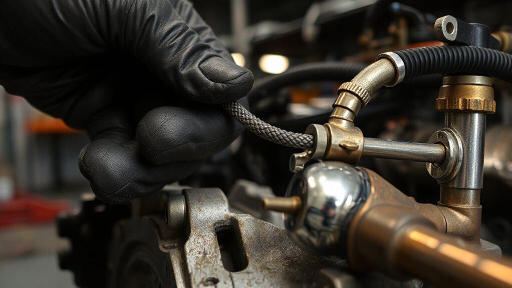
- Locate the passenger‑side kickdown cable housing, ensure the rubber seal is intact, and release the latch with a screwdriver if needed.
- With the throttle fully open, pull the inner wire to remove slack, slide the housing down, and lock the latch firmly, confirming an audible click.
- Verify throttle‑position sensor wiring: constant 5 V supply and varying signal wire, using a multimeter for reference.
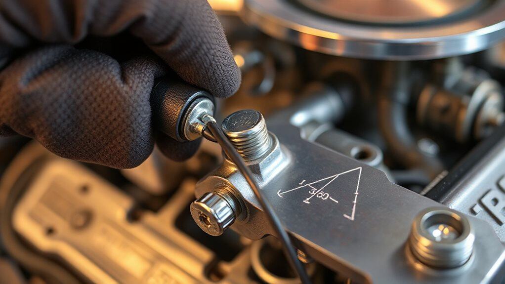
- Adjust the modulator screw in quarter‑turn increments, road‑testing after each turn to observe RPM changes (≈200‑300 RPM per full turn).
- Fine‑tune shift points by moving the housing rearward in 1/8‑inch steps, locking after each move, and confirming gear engagement timing on the road.
Locate the Kickdown Cable Housing & Locking Tab
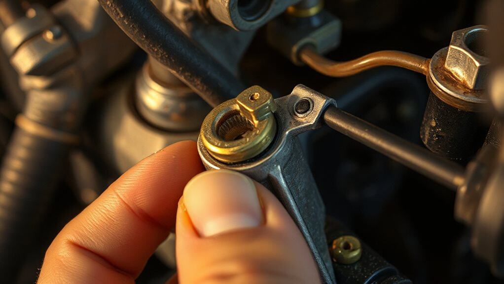
The kickdown cable housing sits on the passenger‑side front of the transmission, where a retaining bolt secures it to the transmission housing at factory‑specified torque. You’ll see a rubber hat seal coating the housing, its lip positioned at the top, keeping fluid out. The inner cable hole aligns with the transmission hookup rod. Locate the latch on the housing; it pushes down to lock, and you may need to pry it up with a screwdriver if it sticks. Hold the throttle wide open while locking to prevent pull. Choose the fiberglass dune buggy body that matches your terrain to avoid costly mistakes and ensure proper performance, such as selecting a sand rail for loose sand areas.
Prepare Engine & Throttle Linkage for Safe Adjustment
Where do you begin before touching the kickdown cable? Turn the engine off and keep it off while you work. Verify the throttle returns fully to idle, then press the accelerator slowly to floor, confirming the pedal reaches wide‑open throttle without binding. Inspect the linkage for wear, ensure smooth movement, and route the cable through the carburetor bracket, aligning it to avoid interference. Release the spring tab after confirming full extension. Remember that the kickdown cable primarily signals downshift and does not control line pressure. Also inspect nearby seals and linkages for signs of wear or corrosion to prevent operational issues.
Base Pull‑Tightening Adjustment for Kickdown Cable
First, verify the throttle is fully open so the cable experiences maximum pull; this assures your tension readings are accurate.
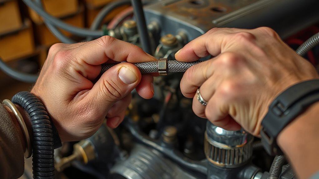
Next, adjust the cable tension by pulling the inner wire toward the transmission until all slack is removed, then slide the housing down while keeping the pull tight.
Finally, secure the latch tab firmly in its locked position, confirming it clicks into place and won’t slip during operation.
Throttle Position Verification
Ever wondered how to confirm the throttle position sensor (TPS) is correctly wired before tightening the kickdown cable? First, set your multimeter to 20 V DC, ground the black lead, and probe each connector wire while the ignition is on. Identify the constant 5‑V supply wire, then back‑probe to locate the signal wire that varies as you press the pedal. Record the wires for later reference.
Cable Tension Adjustment
When you’ve secured the lock tab and slid the cable housing fully toward the transmission, the next step is to set the base tension so the kickdown cable engages correctly at wide‑open throttle (WOT).
Depress the pedal to WOT, pull the housing as tight as possible, then slide it down and lock it.
Release the pedal; the sleeve should click, confirming snug tension.
This establishes the baseline for precise shift timing.
Locking Tab Securing
How do you secure the locking tab after setting the base tension on the kickdown cable? Push the D‑shaped tab down firmly until you hear a click, confirming it seats fully.
Apply steady pressure, then try moving the cable slightly; if it resists, the lock engaged.
Finally, release the throttle pedal and double‑check the cable stays in position without slipping.
Verify Full‑Throttle Tension & Release Locking Tab
What you need to confirm now is that the kickdown cable stays tight only when the throttle is at its wide‑open position and that the locking tab re‑engages correctly after you release it.
With the engine off, rotate the throttle to WOT, pull the housing forward until it locks, then let the throttle return to idle. Observe that the tab snaps flush, the cable relaxes, and no slack remains at full throttle. Verify the tab seats without protrusion and the tension simulates at least 90% throttle activation. Regular maintenance like replacing the cabin air filter can prevent unrelated HVAC issues and improve overall vehicle performance, including ventilation effects on throttle feel during long drives with cabin air filters.
Test Initial Road Shift Points
You’ll start by checking the shift timing as you accelerate, noting the exact RPM at which each gear engages.
While driving, observe how smoothly each gear locks into place and whether any hesitation or jerking occurs.
If you notice delays, record the RPM and gear number, then compare those figures to the manufacturer’s specifications to determine if further adjustment is needed.
Multiple warning lights appearing together on your Nissan Altima signals a serious alternator problem that could leave you stranded within minutes, so be alert for alternator trouble if electrical issues accompany shifting symptoms.
Verify Shift Timing
When you pull the bike onto a quiet road and let it idle, you can start checking the shift timing by noting the speeds at which the transmission moves from first to second gear and from second to third gear. Record the mph for each shift, compare to typical 20 mph (1‑2) and 30 mph (2‑3) points, and watch for early jumps caused by vacuum leaks or a worn modulator O‑ring.
Adjust the modulator screw inward for earlier shifts or outward for later ones, then retest until the observed speeds match the expected values for your rear gear ratio.
Observe Gear Engagement
How do you verify that the TH350’s kickdown cable is correctly setting the initial road shift points? Start the car on a flat surface, engage Drive, and accelerate gently. Listen for a smooth, immediate gear change without hesitation. Feel the engine speed drop as the transmission downshifts. If the shift feels delayed or the engine revs high, the cable needs fine‑tuning. Adjust incrementally, retest, and repeat until shifts occur promptly at the intended RPM.
Note Any Delays
After confirming the cable lets the transmission engage smoothly, you need to record any lag between the accelerator input and the actual gear change. Cruise at about 20 mph and note when the shift from 1st to 2nd occurs; if it’s later than expected, a delay exists. Do the same at 30 mph for 2nd‑to‑3rd. Compare these MPH values to the expected shift points for your rear‑gear ratio and vacuum modulator setting. Write down each observed shift before you adjust the cable or modulator, and watch for early upshifts that indicate a possible governor or leak issue.
Fine‑Tune Late Shifts by Moving Housing Forward
Ever wondered why your TH350 still shifts late even after adjusting the vacuum modulator? Move the transmission housing forward a few millimeters to shorten the kick‑down cable’s effective length. Loosen the housing bolts, slide the housing forward, then retighten. This reduces cable slack, causing earlier shift engagement. Re‑check vacuum, then repeat if necessary, ensuring smooth upshifts under load. Check the battery and electrical connections regularly to avoid starting problems with modern push-button systems and related components like the key fob battery.
Re‑Test After Each Forward Increment
After you move the cable housing forward by 1/8 inch, you must immediately perform a road test to verify the shift change. This incremental shift verification lets you see whether the passing gear now engages at full throttle and whether early‑shift sensitivity has been reduced.
Consistent results across multiple test cycles confirm that the adjustment is correct before you proceed to the next increment.
Incremental Shift Verification
How do you confirm that each forward increment of the kickdown cable is actually moving the shift points as intended? After every quarter‑turn of the modulator screw, test drive shifts and note the RPM rise—typically 200‑300 RPM per full turn.
Shorten the detent cable 1/16 inch, re‑test the 2‑3 shift, and ensure no binding. Verify vacuum line integrity before each re‑test, and repeat until the desired RPM advancement appears.
Road Test Consistency
When you finish a quarter‑turn of the modulator screw, you must immediately road‑test the vehicle to verify that the shift points have moved as expected.
Drive to 30‑40 mph, then downshift manually; watch the RPM drop and note any delay.
Repeat the test after each forward increment, checking pressure, cooler volume, and shift consistency.
This cycle builds heat, confirms cable tension, and isolates timing issues before high‑boost track testing.
Fine‑Tune Early Shifts by Moving Housing Rearward
Why does moving the cable housing rearward help eliminate early shifts?
Shifting the housing back reduces cable pull when you accelerate, so the transmission sees a throttle input that matches the actual pedal position. Slide the housing rearward while the engine is off, lock it with the spring‑loaded tab, and keep the cable taut at full throttle. This mimics greater accelerator input, preventing premature gear engagement before the intended RPM range.
Re‑Test After Each Rearward Increment

What you’ll notice after each 1/8‑inch rearward move is a shift in the timing of gear engagement, so you must verify the change before proceeding. After every adjustment, lock the snap‑lock, then road‑test immediately. Record throttle position when the next gear engages, compare it to the baseline, and check for early upshifts or missing passing gear. If timing isn’t right, repeat the 1/8‑inch step and retest. Estimate remaining driving range using your vehicle’s miles per gallon and tank capacity to ensure you can complete testing without refueling.
Mount Holley 20‑95 Throttle Bracket & 20‑121 Kickdown Bracket
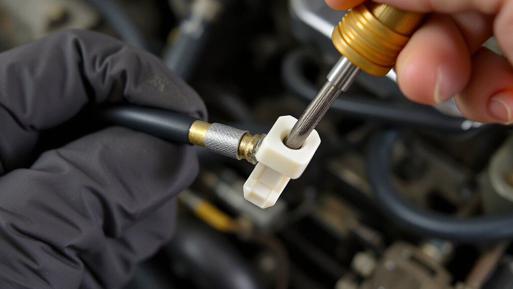
After you’ve confirmed the timing shift from each rearward increment, the next step is to install the Holley 20‑95 throttle bracket together with the 20‑121 kickdown bracket. Align the 20‑95’s set‑screw hole with the carburetor flange ear, then loosen its bolt, position the bracket, and tighten to prevent rocking. Mount the 20‑121 similarly, ensuring both brackets securely hold their respective cables.
Attach Throttle‑Valve (TV) Cable to Stud, Align Geometry
How do you attach the throttle‑valve (TV) cable to the stud and align the geometry correctly? Pull the cable front toward the vehicle’s front, slide the slot over the throttle‑linkage stud, and, if needed, add the extender. Tighten the #10‑32 button‑head bolt with a nylock nut, then back it off slightly so the slot slides freely. Release the latch, move the throttle to wide‑open, lock the housing, and verify full opening without binding.
Final Road Test & When to Call a Pro
When you finish the fine‑tuning steps, the final road test confirms whether the Th350 kickdown cable is properly set or not.
Accelerate hard, watch for immediate downshift at wide‑open throttle, and note any high‑rev hesitation.
Ensure the pedal returns smoothly.
If shifts remain erratic after several 1/8‑inch tweaks, the cable is damaged, or transmission symptoms persist, consult a professional.
Wrapping Up
By following each step, you’ll have the kickdown cable on your TH350 set to the correct tension, ensuring smooth throttle response and reliable shift points. Double‑check the locking tab, verify full‑throttle tension, and run a road test to confirm the adjustments hold. If the cable still drifts or the transmission hesitates, consult a professional mechanic. Proper setup reduces wear on the throttle valve and improves overall drivability.