
A bad alternator can indeed cause transmission problems because it deprives the transmission control module (TCM) of steady voltage, forcing the system into limp‑mode. When the alternator’s output falls below roughly 13.5 V, the TCM cannot meet the voltage thresholds needed for gear changes, so shifts are limited or halted. Excessive AC ripple from a failing diode corrupts sensor signals, leading to false speed readings and protective fault codes. You’ll notice dimming lights, a battery warning, and possibly a whining noise at idle. Checking voltage with a curb‑side tester or oscilloscope, and inspecting diodes, wiring, and grounds, will confirm the fault. Continuing will reveal how to diagnose and prevent these issues.
Quick Tips
- A failing alternator can starve the TCM of steady voltage, triggering limp‑mode and restricting gear changes.
- Voltage drops below ~13.5 V cause the PCM/ECU to suppress shifts, flash PRNDL, and cap engine speed for protection.
- Excessive AC ripple from a bad rectifier distorts sensor signals, leading to false speed readings and transmission error codes.
- Diagnostic signs include flickering headlights, battery‑warning light, low idle voltage, and OBD‑II codes such as P0562 and P2503.
- Regularly testing alternator output (13.7–14.7 V), checking wiring/grounds, and maintaining proper transmission fluid prevent voltage‑related transmission issues.
How a Bad Alternator Triggers Transmission Limp‑Mode
When an alternator starts to fail, it can starve the transmission control module (TCM) of the clean, steady voltage it needs to run properly, and that voltage dip is often enough to push the transmission into limp‑mode. The TCM then receives erratic power, triggering fail‑safes that limit gear selection. You’ll notice PRNDL flashing, reduced RPM, and a capped speed while the system protects itself. Weak battery can also exacerbate the issue, causing additional voltage fluctuations that further destabilize the TCM. Regular inspection of charging and electrical components, including the alternator and battery, helps prevent these faults by ensuring steady voltage supply.
Why Low System Voltage From a Bad Alternator Stops Gear Shifts
When the alternator can’t keep the system voltage above the transmission’s minimum threshold, the control module can’t generate reliable shift commands, so the gearbox stays in limp‑mode or refuses to change gears.
The excessive AC ripple that a faulty diode introduces also corrupts sensor signals, especially the speed sensor, causing the ECU to interpret erroneous data and halt shifting.
As a result, you’ll notice harsh or missing shifts until the voltage stabilizes or the alternator is repaired.
In some cases, low voltage can also cause ancillary systems like the HVAC to underperform, which may indirectly affect engine and transmission cooling and load management.
Voltage Threshold for Shift Logic
Why does a weak alternator keep your car stuck in gear? The PCM watches system voltage and only allows shift commands when it stays above a preset threshold, typically 13.5 V. If the alternator can’t maintain that level, the PCM suppresses gear changes to protect the transmission.
Duty‑cycle signals from the alternator’s field circuit inform the PCM whether voltage is sufficient, and below‑threshold readings pause shifting until voltage recovers.
Ripple Effects on Sensors
Ever notice how a weak alternator can make your car’s sensors misbehave, ultimately halting gear changes?
Excessive AC ripple—over 50 mV—contaminates the speed sensor’s voltage waveform, producing false readings that the TCM interprets as sensor errors.
This distortion triggers diagnostic codes, forces limp‑mode, and prevents proper gear shifts.
Measuring ripple at 1500 rpm with a multimeter reveals the problem.
ECU Response to Low Power
A weak alternator that lets the system voltage dip below the ECU’s minimum threshold will immediately affect the transmission’s electronic control unit (ECU).
The ECU needs stable DC; when voltage falls, it locks out higher gears and forces limp‑mode 2nd gear.
Solenoid control stops, speed sensor signals become erratic, and gear shifts cease until voltage recovers.
How AC Ripple Misreads Transmission Sensors
When AC ripple from a failing alternator rides on the vehicle’s power bus, it adds unwanted voltage fluctuations to the sensor signals that the transmission control module (TCM) relies on. This distortion can cause the output speed sensor to report phantom speeds—like a 20 mph reading while the car is parked—leading the TCM to misinterpret gear position and trigger limp‑mode behavior.
AC Ripple Interference
Ripple voltage from a failing alternator diode contaminates the power rails that feed the transmission control module, turning a clean DC supply into a noisy, fluctuating waveform. This AC ripple creates asymmetric waveforms, preventing sensors from receiving stable reference voltages.
The resulting electromagnetic interference injects false signals, causing the control module to misinterpret data and potentially reset or trigger erratic shifting.
Sensor Signal Distortion
Why does a transmission sensor suddenly report erratic speeds or gear positions?
The alternator’s failing diode injects AC ripple into the DC bus, superimposing a 50‑100 mV oscillation onto sensor power rails.
This distortion skews the voltage waveform the speed sensor sends to the control module, making it read false pulses.
You’ll see jittery PWM signals and missing peaks on an oscilloscope, confirming the interference.
Replacing the alternator eliminates the ripple and restores accurate sensor data.
Identify Diode Failure Symptoms and Diagnostic Signs
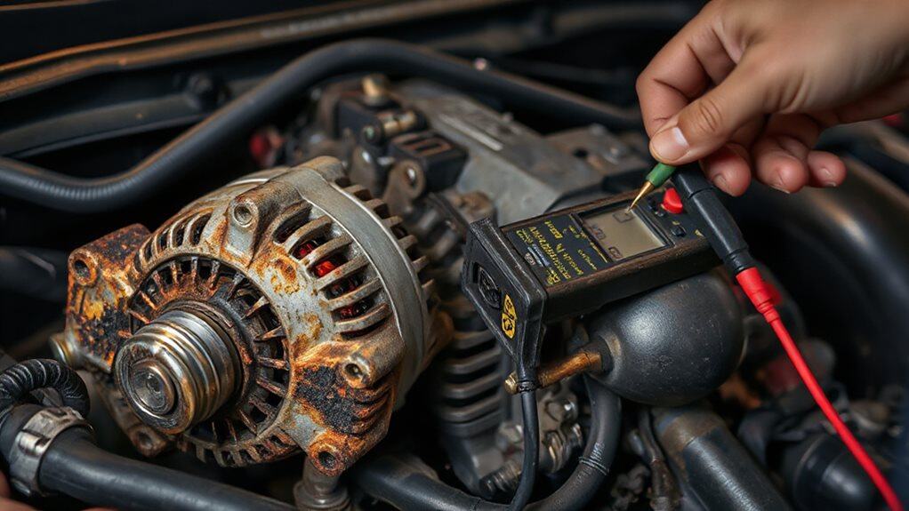
Do you recognize the tell‑tale signs that a faulty alternator diode is disrupting your vehicle’s electrical system? You’ll see the battery warning light, flickering headlights, and erratic dashboard lights. Voltage may drop at idle, and a whining noise may emerge. Multimeter reverse‑leakage tests reveal current flowing backward, indicating a shorted or open diode. Replace the diode assembly promptly.
Measure Alternator Ripple With an Oscilloscope
How do you capture the tiny voltage fluctuations that reveal an alternator’s health? Connect the oscilloscope probe to the alternator B+ terminal, use an AC‑coupled filter to block DC, and attach the black lead to the negative battery post. Set idle at ~1,500 rpm, then increase load with headlights and fan. Adjust vertical scale to 1 V AC, observe asymmetric waveforms, and compare ripple (0.10‑1.00 V AC) to acceptable limits. Persistent electrical faults can also affect other vehicle systems and may produce misfire-like symptoms that require prompt diagnosis.
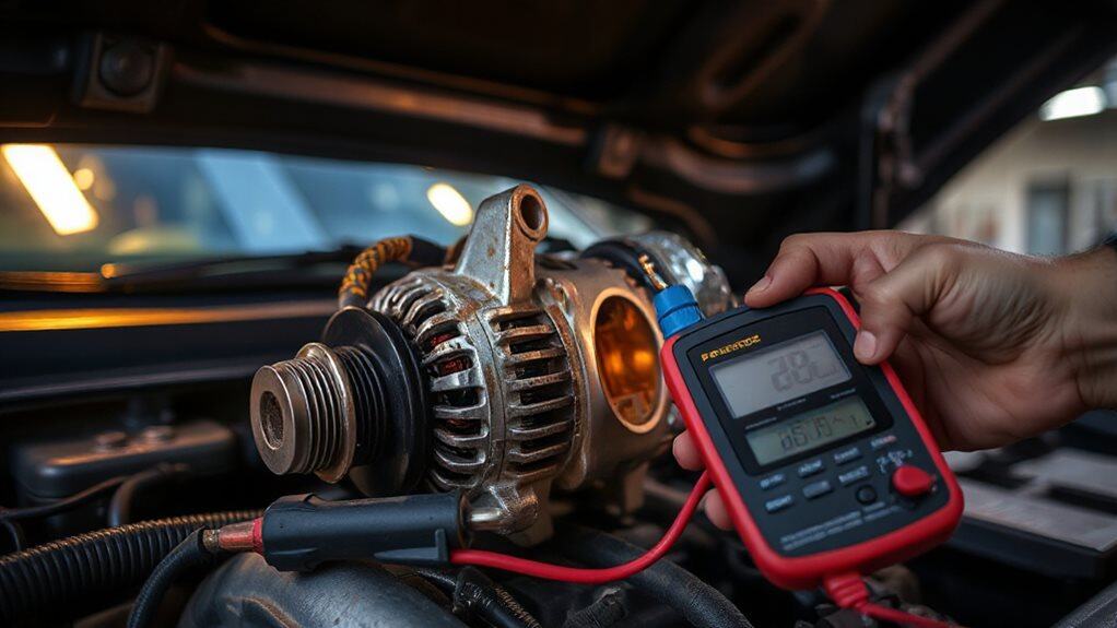
Compare Voltage at the Alternator vs. Battery Terminals
When you measure the alternator’s output directly at its terminal, you’ll usually see 13.7–14.7 V with the engine running, while the battery terminals typically sit a volt or two lower because of cable resistance and load.
If the reading at the battery drops below about 13 V while the alternator still shows a healthy voltage, the discrepancy points to wiring, belt, or grounding problems rather than a weak alternator itself.
Comparing these two values lets you quickly isolate whether the issue lies in the alternator’s generation capacity or in the downstream electrical path.
Regular alternator checks can identify problems weeks or months before failure, helping schedule repairs and avoid being stranded roadside with early detection of charging system issues.
Alternator Output Voltage
What’s the real difference between the voltage you read at the alternator’s terminals and the voltage showing on the battery’s terminals?
The alternator typically outputs 13.8‑14.4 V, regulated by its internal controller or the ECM, while the battery sees a slightly lower, steadier voltage as it charges.
RPM, temperature, and load shift the alternator’s output, but you should never see less than about 13.2 V under load.
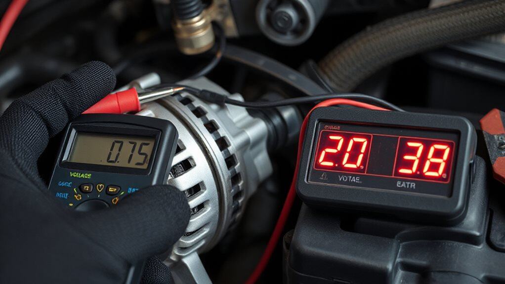
Battery Terminal Voltage
Ever wondered why the voltage you measure at the alternator’s B+ post is often a few tenths of a volt higher than the voltage you see at the battery terminals?
The alternator typically shows 13.55 V, while the battery reads 13.36 V, revealing a 0.19 V drop across the positive lead.
Negative‑side drops stay under 0.03 V, confirming solid grounds.
Compare dash readouts with terminal readings; a 0.3 V discrepancy often signals a fusible‑link issue.
Isolate the Alternator With a Control‑Circuit Test
How do you verify that the alternator’s control circuit isn’t the source of a charging problem? Start by measuring the voltage drop between the alternator’s positive output terminal and the battery’s positive terminal while the engine runs; a multimeter set to DC volts should read less than 0.2 V, indicating minimal resistance in the wiring and connectors. Next, check the ground side: place one probe on the alternator case and the other on the battery negative. The drop also stays under 0.2 V, confirming a healthy control circuit. If either reading exceeds this threshold, inspect connectors, wires, and the regulator plug for faults before proceeding. Improving insulation quality can significantly reduce overall electrical load and help maintain consistent system performance.
Use a Curb‑Side Tester to Check Alternator and Battery Health

Can a curb‑side tester quickly reveal whether both the alternator and battery are functioning properly? First, turn the engine off and check the resting voltage; a healthy battery reads 12.4‑12.7 V. Then, start the engine and observe the tester’s reading—13.5‑14.5 V indicates proper alternator output. Finally, turn on headlights and AC; if voltage stays between 13‑14 V, the system passes the load test. For winter driving, also inspect cold-rated components like cold‑rated jumper cables and ensure battery and charging equipment perform at low temperatures.
Interpret Curb‑Side Test Results for Alternator Health
After confirming the resting voltage with the engine off, you move on to interpreting the readings you gathered while the engine runs. If idle voltage sits between 13.5‑14.5 V, the alternator charges properly; below 13.2 V signals undercharging. Readings staying near 12.6 V or dropping suggest no charging. Above 14.6 V indicates regulator overcharge.
AC ripple above 0.3 V points to a failed rectifier. Voltage drops over 0.3 V on the positive side or 0.2 V to ground reveal resistance issues.
Other OBD‑II Codes That Appear When the Alternator Fails
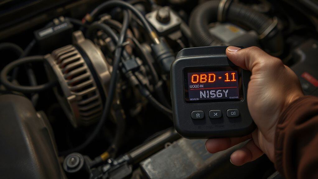
When the alternator begins to fail, the vehicle’s diagnostic system often logs several OBD‑II trouble codes that go beyond the obvious “alternator” codes. You’ll see P0562 for low system voltage, P2503 for charging‑system malfunction, P0613 indicating TCM trouble, P0600 for ECU issues, and P0700 for general transmission faults. These codes point to voltage drops that disrupt multiple control modules, not just the alternator.
Preventive Maintenance to Keep Your Alternator Transmission‑Ready
How can you keep your alternator and transmission working together without unexpected failures?
Regularly inspect fluid levels, ensuring the transmission fluid is clean, properly filled, and matches the vehicle‑specific formula; replace it per the manufacturer’s schedule.
Avoid overloading the vehicle, respect weight limits, and practice gentle shifting—stop fully before changing direction.
Schedule professional inspections to catch leaks, worn parts, or voltage issues early, and test the battery and alternator at a local auto parts store.
Wrapping Up
A faulty alternator can indeed force your transmission into limp‑mode by dropping system voltage, corrupting sensor signals, and triggering OBD‑II codes. Monitoring ripple, checking diode health, and performing curb‑side tests let you pinpoint the issue before it harms the gearbox. Regularly inspecting the alternator and battery, and addressing low‑voltage warnings promptly, will keep both the electrical system and transmission operating smoothly. Stay proactive to avoid costly repairs.


