
To test an ignition coil with a multimeter, start by setting it to measure resistance (Ω). Disconnect the coil from your vehicle to prevent false readings. Measure the primary circuit resistance by connecting probes to the coil’s primary terminals; typical values range from 0.2 to 3 ohms. For the secondary, connect the probes to the high-tension terminal and ground, expecting 6,000 to 30,000 ohms. Variations outside these ranges suggest faults, and further testing during engine operation can confirm proper voltage output. Continuing will uncover detailed testing procedures and troubleshooting tips.
Quick Tips
- Set the multimeter to resistance (Ω) mode and disconnect the coil from the vehicle.
- Locate the primary and secondary terminals and connect the multimeter probes accordingly.
- Measure primary resistance between the B+ and C terminals; expect 0.2 to 3 ohms.
- Measure secondary resistance between the high-tension terminal and ground; expect 6,000 to 30,000 ohms.
- Compare readings to specifications; deviations indicate potential coil faults or damage.
Prepare Your Multimeter for Ignition Coil Testing
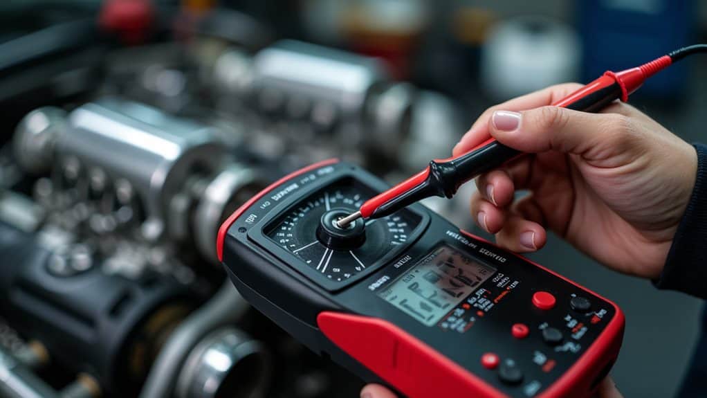
Before testing your ignition coil, you need to properly prepare your multimeter to guarantee accurate measurements.
Set your digital multimeter to the resistance (Ω) mode to measure coil windings precisely.
Make certain the probes are clean and make good contact with the coil terminals.
Disconnect the coil from the vehicle’s electrical system to prevent false readings or damage.
Also, ensure you verify the correct probe placement and settings by referencing the compatible hose sizes and multimeter manual for sizing and compatibility guidance.
Identify and Disconnect Your Ignition Coil Safely
Begin by locating the ignition coil in your engine bay, which is typically found near the distributor or spark plugs. Make certain the engine is completely off before proceeding.
Next, disconnect the electrical connectors attached to the coil carefully to prevent any accidental short circuits. Remove any spark plug wires connected to it to access the terminals.
Verify that all power sources are disconnected and that the ignition key is in the off position to safely disconnect the coil without risking electrical shock or damage. Hub-centric spacers ensure even weight distribution across the hub assembly, reducing stress on wheel bearings and improving stability at high speeds for better vehicle handling.
Locate Ignition Coil Properly
How can you accurately locate your vehicle’s ignition coil and guarantee it’s safely disconnected for testing?
First, locate the ignition coil in your engine bay, usually near the spark plugs or cylinder head.
Identify the primary and secondary terminals, then disconnect electrical connectors and spark plug wires.
Following manufacturer guidelines *assures* safe and correct identification for testing.
Disconnect Electrical Connections
Are you ready to disconnect the electrical connections from your ignition coil safely and correctly? Make certain the ignition switch is off.
Then carefully identify the primary terminals labeled B+ or 15 for power and C or 1 for ground.
Disconnect all wiring, verifying they’re fully detached with a multimeter set to resistance mode, preventing false readings or damage.
Ensure Engine Is Off
Confirming the engine is completely off before working on the ignition coil is a crucial safety step that should never be overlooked. You must verify the ignition switch is in the “off” position and remove the key.
Additionally, confirm the engine has cooled to avoid burns.
Disconnecting the electrical connector isolates the coil, preventing accidental electrical shocks or damage.
Measure the Primary Resistance of the Ignition Coil
Before measuring the primary resistance of the ignition coil, it’s important to disconnect the coil from the vehicle’s electrical system.
Set your multimeter to ohms (Ω), then connect the probes to the primary terminals, usually labeled B+ and C.
The typical primary resistance ranges from 0.2 to 3 ohms, depending on the coil specifications.
After testing, if readings are inconsistent you should also inspect for possible electrical issues like wiring problems that can affect coil performance.
Check the Secondary Resistance of the Coil
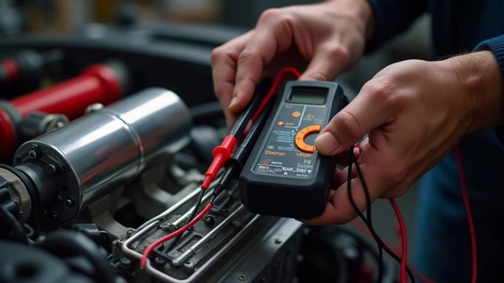
To check the secondary resistance of an ignition coil, connect your multimeter’s probe to the coil’s high-tension (HT) terminal and the other probe to the negative terminal or ground.
The secondary resistance typically ranges from 6,000 to 30,000 ohms.
Deviations from manufacturer specifications can indicate internal faults, such as shorts or open circuits, affecting coil performance.
For improved accuracy, ensure the coil and surrounding surfaces are clean and dry before testing and avoid moisture contamination which can affect readings.
What Do Resistance Readings Tell You?
Resistance readings reveal whether an ignition coil’s internal windings are intact or damaged; values markedly outside the specified range typically indicate faults.
For primary coils, expected readings fall between 0.2 and 3 ohms, while secondary coils should measure between 6,000 and 30,000 ohms.
However, normal resistance doesn’t guarantee proper operation, so visual inspection and functional testing are also essential.
Tire size and load considerations can affect vehicle handling and electrical load distribution, so check your vehicle’s load index when selecting replacement components.
Normal Resistance Values
Typical resistance values for ignition coils provide a baseline for evaluating their condition, but they don’t guarantee proper operation on their own.
For ignition coils, primary resistance usually ranges from 0.2 to 3 ohms, while secondary resistance falls between 6,000 and 30,000 ohms.
Deviations from these ranges may indicate internal faults, but always compare readings with manufacturer specifications for accurate diagnosis.
Indications of Coil Faults
When testing an ignition coil, resistance readings can reveal important clues about its condition, but they don’t tell the whole story.
If the coil’s resistance between primary pins is around 0.6 ohms, it’s likely healthy.
Higher or lower readings—such as 1.2 ohms or abnormal secondary resistance—may indicate internal faults, shorts, or open circuits within the coil.
Test the Coil’s Voltage Output During Engine Run
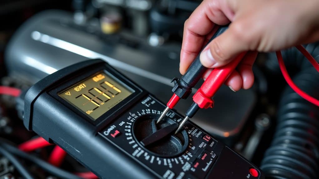
To test the coil’s voltage output during engine run, you need to set up your multimeter correctly and carefully observe the voltage produced by the ignition system.
Connect the probes to the spark plug wire boot and ground.
Start the engine, and verify a smooth idle.
The voltage should typically read between 20,000 and 50,000 volts, indicating proper coil operation.
Remember that the ignition coil is a movable electronic device that is considered personal property rather than a permanently installed fixture.
Troubleshoot Ignition Coil Problems Based on Test Results
Analyzing your test results carefully is essential when troubleshooting ignition coil problems, as deviations from expected resistance readings can point to specific issues within the coil’s internal structure.
If resistance between B and A or C pins is around 0.6 ohms and A to C is about 1.2 ohms, the coil is likely healthy.
Significant deviations suggest faults like open or shorted windings, indicating the need for further inspection or replacement.
When to Replace Your Ignition Coil
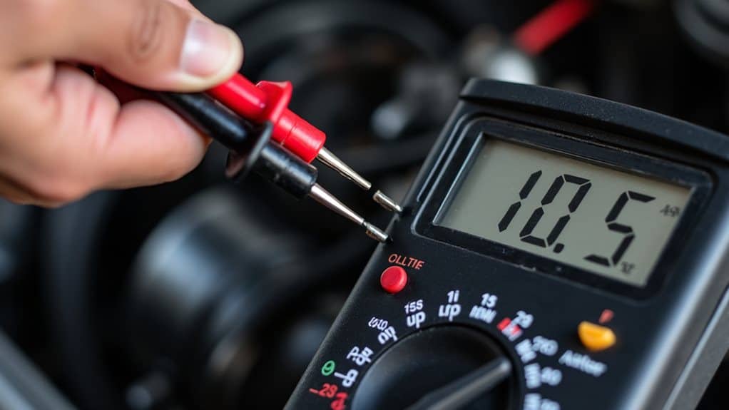
Determining the right time to replace your ignition coil is essential for maintaining engine performance and avoiding further damage.
If resistance measurements fall outside manufacturer specs—such as primary resistance below 0.2 ohms or abnormal secondary resistance—you should replace the coil.
Visible damage or persistent misfires also indicate it’s time for a replacement to guarantee reliable engine operation.
Wrapping up
Testing your ignition coil with a multimeter involves measuring its primary and secondary resistances, as well as checking voltage output during engine operation. Accurate readings help determine if the coil is functioning properly or needs replacement. Always disconnect the coil safely before testing to prevent damage or injury. Interpreting resistance values and voltage results provides understanding into coil health. Regular testing can prevent ignition failures, ensuring reliable engine performance and avoiding unnecessary repairs.