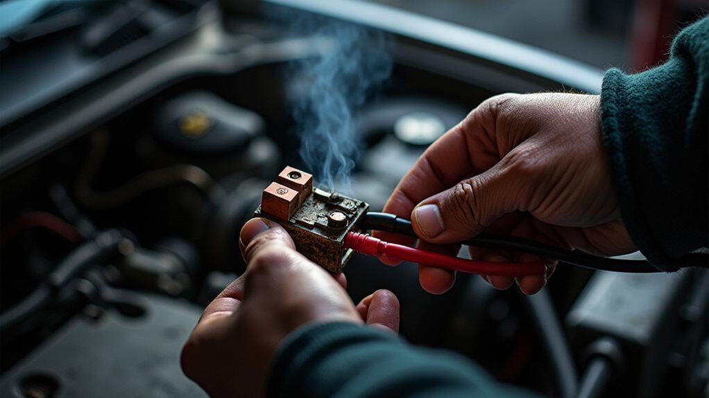
You’ll first confirm the battery is ≥12.6V, set the transmission to Park/Neutral, engage the parking brake, and have an assistant ready; disconnect the negative terminal for ground removal until you’re set. Locate the under‑hood starter relay (marked ST/Starter/IGN), inspect for corrosion, then turn the ignition to RUN and briefly bridge terminals 30 and 87 with an insulated tool for 1–2 seconds, stop if smoke or abnormal noise occurs, restore the relay and battery, and continue for detailed guidance.
Quick Tips
- Verify battery voltage ≥12.4V, secure vehicle in Park/Neutral, engage parking brake, and use wheel chocks before any bypass attempt.
- Disconnect the negative battery terminal to de-energize the primary circuit until you’re ready to momentarily test.
- Identify the starter relay socket (pins 30 and 87) using the fuse-box schematic or owner’s manual before touching terminals.
- With ignition ON, briefly bridge terminals 30 and 87 using an insulated, fused jumper or insulated screwdriver for 1–2 seconds only.
- Stop immediately and reconnect battery if you see burning, smoking, melting, no sound, or abnormal electrical behavior; replace relay/socket as needed.
Safely Bypass the Starter Relay (Quick Emergency Test)
Before you begin, make sure you’ve taken all required safety and preparation steps so the quick emergency test can be performed without creating a larger hazard.
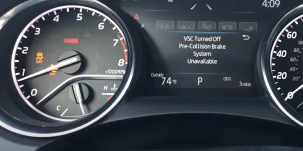
You’ll confirm battery voltage (≥12.6V), set transmission to Park/Neutral, turn ignition to ON, and clear tools from moving parts. Note that on some vehicles the starter control is integrated into the TIPM, which may affect how the starter circuit behaves during testing.
Use an insulated screwdriver or fused jumper, have an assistant, bridge terminals only briefly, then stop immediately.
Always disconnect the negative battery terminal to remove the ground path and de-energize the primary circuit disconnect the negative battery.
Locate the Starter Relay Under the Hood
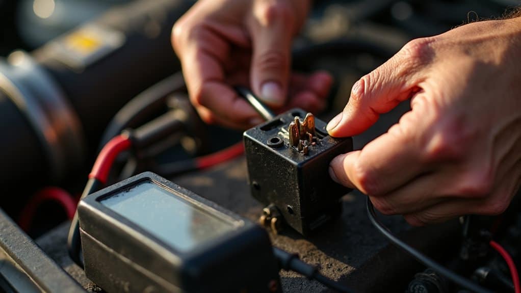
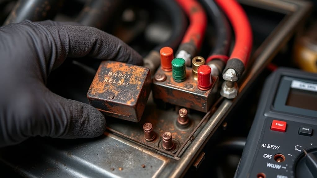
First, open the hood and locate the under-hood fuse box—it’s usually a black plastic box near the battery or mounted on the engine wall, and some cars put it on the driver’s side near the firewall. Remove the cover and match the schematic printed on the underside to the grid of relays; the starter relay is often labeled “ST”, “Starter”, or “IGN” and looks like a roughly 1″ square black “ice cube” relay.
If you can’t find it by eye, check your owner’s manual or a maker-specific diagram, and remember that some vehicles have multiple fuse boxes or similarly sized relays, so verify the relay position before you touch any terminals.
Moisture-driven corrosion can seize electrical components over time, so inspect surrounding relays and connectors for signs of corrosion and rust.
Fuse Box Location
Where should you look under the hood to find the starter relay?
Check the engine bay fuse box near the battery or firewall, often on the driver’s side or left fender well.
Lift the black plastic cover by squeezing side tabs, then inspect the rear of the box for a large relay beside the 30‑amp starter fuse; diagrams under the lid confirm positions.
Relay Identification
How do you quickly recognize the starter relay under the hood? Look in the under-hood fuse box near the battery or on the starter solenoid; lids often list START, ST, or SOL.
Relays are cube-shaped, ~20mm, with four or five pins (30/87 load, 85/86 control) and part numbers.
Swap with a known relay or consult the manual diagram to confirm location.
Gather Tools and Safety Gear for the Test
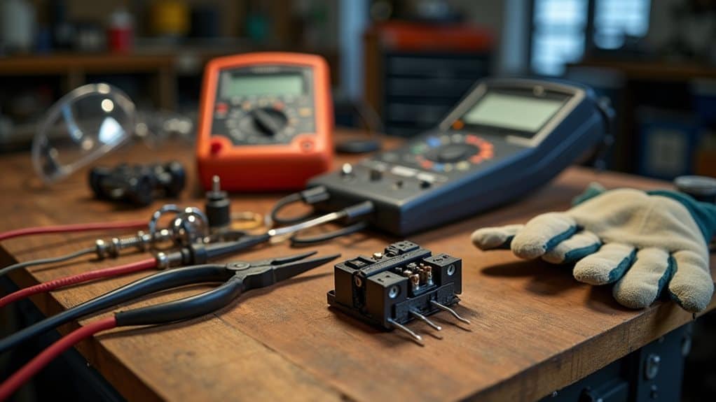
each item serves a defined purpose (shock prevention, eye protection from arcing, and residue-free fire suppression), and having them staged near the vehicle ensures you can perform the test efficiently and safely. Many modern vehicles also benefit from using an OBD2 scanner to diagnose related starting system codes before performing a physical bypass.
Pre‑Checks: Battery, Parking Brake, Transmission, and Visual Inspection
Before you touch any wiring, check the battery’s condition and voltage — it should read about 12.4–12.7 V at rest, and clamps and heavy-gauge cables must be clean and tight to avoid voltage drop under load.
Next, secure the vehicle by engaging the parking brake, placing wheel chocks, and confirming the transmission is in PARK (automatic) or NEUTRAL (manual), plus verify any neutral/seat/PTO interlock switches show continuity.
Finally, perform a visual inspection of starter and wiring for corrosion, exposed conductors, or loose mounts so you can distinguish a relay/control issue from a bad battery, solenoid, or starter motor.
Also confirm the alternator and drive belt show no obvious damage and the belt has proper tension to ensure charging system reliability.
Battery Health Check
A short, systematic battery health check gives you the information you need to determine whether the vehicle is ready for a starter-relay bypass and to minimize electrical or mechanical risk.
Measure open-circuit voltage (12.4–12.6V ideal), verify state-of-charge and CCA match engine needs, inspect terminals and case for corrosion or damage, and confirm no leaks.
Disconnect battery before any bypass work.
Secure Vehicle Position
Now that you’ve checked the battery for voltage, state-of-charge, and physical condition, secure the vehicle’s position before any starter-relay work to reduce risk of movement or unexpected starts.
Park on level ground, set transmission to Park or Neutral, fully engage the parking brake, and chock wheels.
Visually inspect tires, lights, fluids, belts, pedals, seat belts, and horn for safe, reliable operation.
Check for 12V at the Control Terminal to Diagnose the Relay
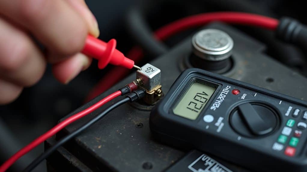
When you’re diagnosing a starter relay, checking for approximately 12 volts at the control terminal (usually pin 85 or 86) tells you whether the ignition circuit is transferring the start signal, so use a digital multimeter set to DC volts and probe the terminal with the key in the start position while keeping a good chassis ground reference.
Read 10.5–12V as correct; zero suggests upstream faults.
Additionally, if you observe no voltage you should inspect related components such as the ignition switch and wiring for continuity and power loss.
Step‑by‑Step: Momentary Bridge of Relay Terminals (How To)
Before you attempt a momentary bridge of the relay terminals, confirm the ignition circuit has been checked for 12 volts at the control terminal so you know the start signal is reaching the relay; this next step lets you directly feed battery power to the starter solenoid to determine whether the relay itself is the fault.
Identify terminals 30 and 87, set transmission and brake, use an insulated screwdriver or fused jumper, turn ignition to RUN, briefly bridge 30 to 87 for 1–2 seconds, observe cranking, remove immediately, wait between attempts, then reinstall relay and clean terminals.
If electrical faults persist, consider inspecting wiring and fuses or consulting a technician experienced with automotive safety systems like sensor alignment.
Signs to Stop Immediately and Safety Faults to Watch For
If you see any signs of burning, melting, heavy corrosion, or a completely silent starter circuit, stop immediately and don’t attempt further bridging or testing until the fault is assessed, because continuing can cause fire, permanent component damage, or personal injury.
Watch for no-click, no-crank, dim lights, blown fuses, high resistance, open coil, melted relay plastic, charred terminals, or intermittent cranking; these indicate unsafe faults requiring inspection.
Why You Must Not Leave a Permanent Bypass and How to Restore the Relay
In practical terms, you must never leave a starter relay permanently bypassed because doing so removes built-in safety controls and creates both mechanical and electrical hazards that can quickly escalate into expensive damage or fire.
You should only bypass briefly for diagnosis, then disconnect the jumper, clean terminals, reinstall the correct relay, reconnect battery negative, and verify operation to restore protection and warranty compliance.
Common Relay Failure Causes and Next Repair Steps
While relays are simple devices, you’ll see failures from a few predictable sources that are easy to diagnose once you know what to look for:
Thermal degradation and contact pitting happen when high current and repeated cranking overheat the internal contacts, leading to increased resistance and eventual loss of conduction;
Corrosion, coil breaks, and mechanical wear also cause clicks, dimming, or no crank.
Test coil resistance, continuity, voltage at pin 87, then replace the relay, inspect the socket, add dielectric grease, and tighten battery connections.
Wrapping Up
You’ve learned to locate the starter relay, confirm battery and transmission settings, and test for 12V at the control terminal; now, if the relay fails, briefly bridge the correct terminals only as a diagnostic emergency, watching for sparks, smoke, or abnormal sounds. Don’t leave a permanent bypass—repair or replace the relay promptly and restore factory wiring. Inspect common failure causes like corrosion, stuck contacts, or wiring faults, and follow proper replacement steps for safe, reliable starting.